Beam parameters#
In this section, we’ll review the various parameters that need to be configured to work in q-space. We assume that you’ve collected all the required information from your beamline scientist (wavelength, PONI, sample-detector distance …), but you can also find them in the notebook. We will address the optional case of using a calibration sample to obtain beam information in a next section.
Beamtime/Experimental Setup#
Click on
File > Beamtime/Experimental Setupto open theBeamtime/Experimental Setupwindow.Click on
New Beamtimeand name your experiment. Here, we will usethe name `Tutorial.Important: Once created, you must select the new entry in the
Beamtimelist again to edit it.
We will create two Experimental Setup configurations here, one for each value of the out-of-plane detector angle gamma.
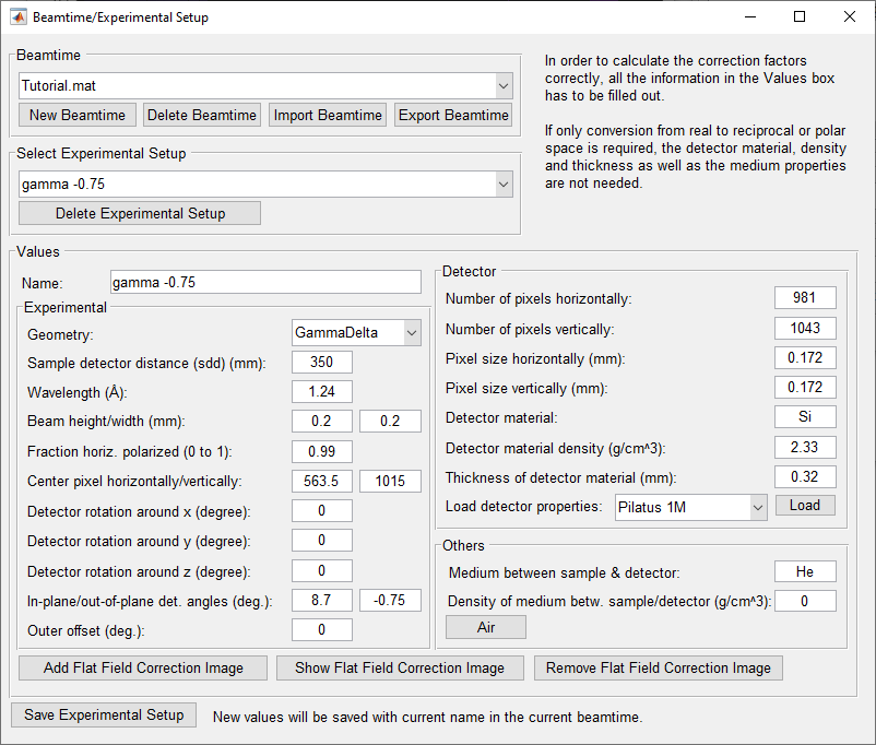
Configuration for \({\rm gamma}=-0.75\)#
In the Name field, enter gamma -0.75 and configure the following parameters:
Geometry:
GammaDelta.Sample detector distance: 350 mm.
Wavelength: 1.24 \(\rm A\).
Beam height/width: Leave as is, not relevant for this case.
Fraction horiz. polarized: 0.99.
Center pixel horizontally/vertically: This refers to the position of the direct beam on the detector, sometimes called PONIx and PONIy (Point Of Normal Incidence). Use values of 563.5 and 1015.
Detector rotation around x, y, z: Leave at 0.
In-plane/out-of-plane det. angles: These correspond to
deltaandgamma, respectively. Note that due to differing conventions, the delta value from the notebook must be inverted for GIDVis. For example, a notebook value of \({\rm delta} = -8.7\) degrees is entered as \({\rm delta} = 8.7\) in GIDVis. Here, use 8.7 and -0.75 degrees.Outer offset: Leave at 0.
Load the detector properties: Select
Pilatus 1Mfrom the list in theDetectorframe and click onLoad.Medium between sample & detector: Set to
Hewith a density of 0.
The parameters in bold are specific to this tutorial and should be adapted for your experimental setup.
Save the experimental setup, and reselect it from the Select Experimental Setup list. The configuration should look like this:
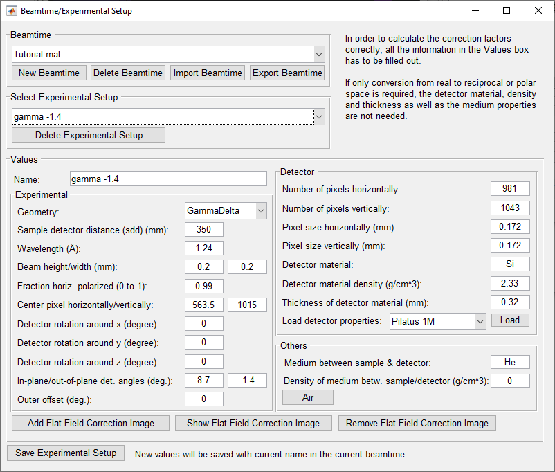
Create one experimental setup per geometry#
Next, create a second Experimental Setup for images collected at \({\rm gamma} = -1.4\) degrees.
Change the out-of-plane detector angle to -1.4.
Update the name to
gamma -1.4.Save the configuration.
This configuration should look like this:
Be sure to save the configuration and close the window.